The basic steps in swaging almost any jacketed bullet are:
- Swage the core to exact weight/size using CSW-1 Core Swage
- Seat the core into the jacket using CS-1 Core Seater
For rebated boattails instead of flat bases... - Seat the core into the jacket using RBT-2 2-die set
For any of the above... - Form the ogive or nose curve using PF-1 Point Former
For lead tips... - Shape the surplus lead at tip using LT-1 Lead Tip

If you would like to see each of these steps detailed, just click the underlined words above. All of the various catalog numbers for swage die sets are made by combining the above dies.
|
 If all you want to do is get the right equipment for a given bullet, send Dave Corbin an e-mail, fax, or letter describing the bullet you want to make. Give a general range of weights, the diameter of the bullet, and a description of any special features you want. You don't have to read or understand any of the information presented here, in order to get the right package. The equipment comes with complete instructions and samples. But if you WANT to know more, read on... If all you want to do is get the right equipment for a given bullet, send Dave Corbin an e-mail, fax, or letter describing the bullet you want to make. Give a general range of weights, the diameter of the bullet, and a description of any special features you want. You don't have to read or understand any of the information presented here, in order to get the right package. The equipment comes with complete instructions and samples. But if you WANT to know more, read on...The most popular set of dies for making jacketed bullets is the Corbin FJFB-3-S or FJFB-3-H, depending on whether you want to use the S-Press (.10 to .458 diameter bullets, up to 1.3 inch OAL) or the larger Mega Mite, Hydro Junior, or Hydro Press (.17 cal to 25mm, virtually any length bullet). 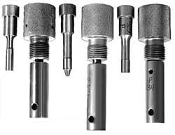 Both the -S and the -H types of dies work the same way. The -H dies are larger and use a 1 inch x 12 thread. The -S dies use a 5/8-24 thread and have a body of from 3/4-inch to 1.0 inch depending on the caliber (small calibers such as .17, .14, .12 and .10 generaly are made with 3/4 inch bodies). Both the -S and the -H types of dies work the same way. The -H dies are larger and use a 1 inch x 12 thread. The -S dies use a 5/8-24 thread and have a body of from 3/4-inch to 1.0 inch depending on the caliber (small calibers such as .17, .14, .12 and .10 generaly are made with 3/4 inch bodies). |
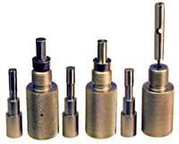
The First Step: Swaging the Core 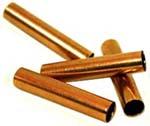 The operation starts with the jacket because the jacket determines the diameter for the core (the filling for the bullet). The solid materials must be small enough to fit inside the jacket before swaging. Very thin jackets, such as those made from fired .22 cases, may only have 0.012 inch thick walls. Thick jackets made from copper tubing may have .035 inch thick walls. Typical commercially made jackets that you can buy in bags of 250 or 500 from Corbin may have walls of .020 to .026 inch thickness (some handgun jackets have thinner walls for faster expansion at low velocities). The operation starts with the jacket because the jacket determines the diameter for the core (the filling for the bullet). The solid materials must be small enough to fit inside the jacket before swaging. Very thin jackets, such as those made from fired .22 cases, may only have 0.012 inch thick walls. Thick jackets made from copper tubing may have .035 inch thick walls. Typical commercially made jackets that you can buy in bags of 250 or 500 from Corbin may have walls of .020 to .026 inch thickness (some handgun jackets have thinner walls for faster expansion at low velocities).The jacket determines the size of the lead core (which must fit inside it). Once the core size is known, then a core swage die (CSW-1) can be made to accept the nearest smaller standard size of wire core. Corbin offers lead wire in standard diameters, core moulds so you can melt scrap lead and cast it into variable weight slugs or cylinders of standard diameters, and lead wire extruders so you can make your own lead wire in any standard or custom size.  Generally, you will want a lead wire sized at least .002 inches smaller than the desired core. The wire can be quite a bit smaller, in fact. The only limit is the length of material needed to make the desired weight. If the core is too small in diameter, it will fold or fail to fit into the die before it is compressed and expanded to the right diameter. The core has to fit completely into the die before any pressure is applied, or it will simply buckle and drive the punch to one side, possibly causing damage when the punch strikes the die face instead of going into the die cavity. Also, the swaged core must fit to the bottom of the jacket, or it may trap air. This is especially problematic in bonding cores, because the heat from bonding may expand trapped air and blow the core out with some force. Generally, you will want a lead wire sized at least .002 inches smaller than the desired core. The wire can be quite a bit smaller, in fact. The only limit is the length of material needed to make the desired weight. If the core is too small in diameter, it will fold or fail to fit into the die before it is compressed and expanded to the right diameter. The core has to fit completely into the die before any pressure is applied, or it will simply buckle and drive the punch to one side, possibly causing damage when the punch strikes the die face instead of going into the die cavity. Also, the swaged core must fit to the bottom of the jacket, or it may trap air. This is especially problematic in bonding cores, because the heat from bonding may expand trapped air and blow the core out with some force.Most .22 and 6mm jackets will accept a .190 core. Some take up to a .204 inch core. But all of these are well within the range of a .185 diameter lead wire. The various .30 caliber jackets take cores of from .251 to .258 inches. Some thick walled jackets made from copper tubing require smaller cores. A wire size of .247 inches allows enough "wiggle room" to get the cut wire into a .251 core swage die. The thicker jacket .30's may require a wire of only .218 diameter, to fit the swage dies from .225 to .235 diameter. You can see that wire size is not critical so long as it fits into the die easily and makes a short enough core for the desired weight. Using lead wire meant for the .224 (.185 diameter) in a .308 die (which makes a .251 core) would not be practical.  The lead core is cast (using the CM-3 or CM-4 core mould) or cut from a roll of wire (using the PCS-1 or PCS-2 core cutter) to a weight just slightly more than desired. To find out the desired weight, weigh the bullet jacket you plan to use. Then subtract the jacket weight from your desired final bullet weight. The difference is the final core weight. Add a few grains, five or so, to this figure, and make your cut or cast cores about that weight. This insures that your rough cores will have enough extra weight so that they can all be slightly reduced in volume to make them all come out exactly the same. If you cut or cast them too close to final weight, the tolerances in cutting or casting might make some of them too light. Then the core swage could not do anything about weight control, as it can only remove lead, not add it. The lead core is cast (using the CM-3 or CM-4 core mould) or cut from a roll of wire (using the PCS-1 or PCS-2 core cutter) to a weight just slightly more than desired. To find out the desired weight, weigh the bullet jacket you plan to use. Then subtract the jacket weight from your desired final bullet weight. The difference is the final core weight. Add a few grains, five or so, to this figure, and make your cut or cast cores about that weight. This insures that your rough cores will have enough extra weight so that they can all be slightly reduced in volume to make them all come out exactly the same. If you cut or cast them too close to final weight, the tolerances in cutting or casting might make some of them too light. Then the core swage could not do anything about weight control, as it can only remove lead, not add it. Lubricate the lead cores lightly using Corbin Swage Lube. You can roll them on a stamp pad that has been saturated with swage lube, or just put a little lube on your finger and thumb tips, and give the cores a twist as you pick them up. It takes very little lube to put an insulating layer between the die and the material being swaged. The thin but tough film of lube prevents leading and reduces wear. Most wear comes from airborne dust that settles on the material you use (jackets or lead). Silica dust is very hard and abrasive. It comes primarily from gravel roads, drifts for hundreds of yards and gets tracked or sucked into the home or workshop through ordinary foot traffic and ventilation systems. If you suspect that there is a high level of silica dust in the air, you can extend your die life by wiping down the lead wire before you use it, and by keeping your bullet jackets and lead supplies in closed containers. Lubricate the lead cores lightly using Corbin Swage Lube. You can roll them on a stamp pad that has been saturated with swage lube, or just put a little lube on your finger and thumb tips, and give the cores a twist as you pick them up. It takes very little lube to put an insulating layer between the die and the material being swaged. The thin but tough film of lube prevents leading and reduces wear. Most wear comes from airborne dust that settles on the material you use (jackets or lead). Silica dust is very hard and abrasive. It comes primarily from gravel roads, drifts for hundreds of yards and gets tracked or sucked into the home or workshop through ordinary foot traffic and ventilation systems. If you suspect that there is a high level of silica dust in the air, you can extend your die life by wiping down the lead wire before you use it, and by keeping your bullet jackets and lead supplies in closed containers.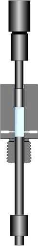 The core swage die (CSW-1-S) has an "S" marked upon it to indicate "core swage". It also has the diameter of core that it produces. Since one core swage can be used for various calibers of bullets, it does not usually have a caliber indicated. The external punch fits into the top of the press. It could be considered the "top punch", but we call it "external" because it stays outside the die all the time, except when swaging takes place. The internal punch is always inside the die. It seals the bottom or threaded end of the die, and is driven upward to eject the finished core when you lower the press ram. The internal and external punches are marked with "S" and the diameter of core, also. They are a snug fit into the die cavity. For details on setting up and using a core swage, see CSW.HTM, the core swage page. In brief, you put the core into the die, raise the ram all the way (make sure the press is in the swaging mode, rather than the longer stroke reloading mode). Adjust the punch holder, in the press head, so that the external punch does not contact the core yet. The punch holder has a bushing that unscrews from the lower end, and fits over the punch. If the punch is larger than .375 diameter (for large calibers), then it will have a built-in hex bushing in the type -S system. The larger -H system does not require a captive bushing until the caliber becomes much larger, in the 12-bore or 70 caliber range. Smaller calibers use the bushing that comes with the punch holder, which in turn comes with the press. Once the ram has been raised to the top of the stroke, lower the punch holder until the punch contacts the core, and you cannot turn it any further down by hand. Then lower the ram and turn the punch holder slightly lower, a quarter turn or so. Raise the ram. Repeat this process until you get a small amount of lead extrusion or encounter resistance. Lower the ram, eject the core, and weigh it. If it is completely filled out and weighs the right amount, you have the correct adjustment. If it is not yet filled out into a nearly perfect cylinder, or is too heavy, continue adjusting and testing until you get the desired weight. Extrusions will come out of the bleed holes. You can use a catcher tray or wipe them into a container so they don't accumulate. Save them to make fragmenting bullets!  Wash the cores in a solvent to remove lube, or boil in hot water and detergent, rinse, and allow them to dry. Put the dry cores into bullet jackets by hand. Then lubricate the jackets with Corbin Swage Lube. Do not get lube inside the jackets. Anything inside the jacket other than the core will tend to cause imbalances during flight. A clean, dry core is the next best thing to a bonded core. You can bond cores at this time if you wish, prior to seating, by applying a drop of Corbin Core Bond into each jacket, placing the jackets in to a ceramic block which has been drilled to hold the jackets upright, and heating the jackets with a propane torch or Corbin's HTO-2 Heat Treatment oven until the lead melts. Instructions for bonding come with each container of Corbin Core Bond. Bonded cores must be cooled, washed, and dryed before seating. Wash the cores in a solvent to remove lube, or boil in hot water and detergent, rinse, and allow them to dry. Put the dry cores into bullet jackets by hand. Then lubricate the jackets with Corbin Swage Lube. Do not get lube inside the jackets. Anything inside the jacket other than the core will tend to cause imbalances during flight. A clean, dry core is the next best thing to a bonded core. You can bond cores at this time if you wish, prior to seating, by applying a drop of Corbin Core Bond into each jacket, placing the jackets in to a ceramic block which has been drilled to hold the jackets upright, and heating the jackets with a propane torch or Corbin's HTO-2 Heat Treatment oven until the lead melts. Instructions for bonding come with each container of Corbin Core Bond. Bonded cores must be cooled, washed, and dryed before seating. |
 |
SEATING THE CORE
Seating the core means compressing the core into a jacket, so that the jacket is expanded to proper size by the pressure on the core. This is necessary so that the jacket will tend to spring back to form a tight grip on the core, and to preset the diameter for best accuracy (it is slightly expanded again in the point forming operation, but not more than about 0.0002 inches in most cases). The core seating die and punches are marked with "C". Don't confuse core swaging, which is the forming of the filler and adjustment of its weight, with core seating. The core is "seated" firmly in the jacket, using an external punch that fits the ID of the jacket at the point where the core ends.
You can see that different wall thicknesses of jackets would require different diameters of external punches, to make a good seal. Otherwise, the pressure (which can reach 20,000 to 50,000 psi in typical swaging operations) would simply blow the lead right past the punch in a thin tube. You might also note that jackets are often tapered or stepped inside, so that the mouth section is thinner than the middle or base. This gives controlled expansion at different ranges and speeds, but it also means that even with the same jacket, you may need a different punch to seat a short core and a long core. Core length is directly related to weight. A heavier bullet usually means that the core comes closer to the jacket mouth than it would in a lighter bullet. This in turn means that the punch which seals the pressure and expands the jacket from pressurized core material has to be larger to fit near the thin mouth section, and smaller in diameter to fit deeper inside the thick middle section of the jacket. Light bullets mean larger diameter core seating punches, heavy bullets mean smaller diameter punches, as a rule of thumb.
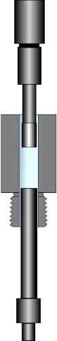
If your punch does not fit closely enough, it will result in an undersized bullet. The reason is that a punch that is too large for the core length will strike the jacket wall and dig into it, rather than making the core flow under pressure. This may wrinkle or shorten the jacket, but it usually won't expand it evenly. The bullet then comes out undersized. Too small a punch for the core length means the lead will bleed around it, releasing the pressure too soon. This also fails to expand the jacket properly and results in undersized bullets.
Obviously, if the set of dies is made for one jacket and weight of bullet, it may not be ready to make a different weight or use a different jacket, without adding a different diameter of core seating punch. There is some latitude, depending on the amount of taper or lack of it in a given jacket. If the jacket wall is straight or nearly so, then one punch diameter will fit over a very wide range of core lengths (and weights). If the jacket wall is very tapered or has a big step in it, then at least two external core seat punches may be required for making the maximum and minimum weights in that jacket. This is why we say the design starts with the jacket. Fortunately, it is easy to make a different punch...just send a sample jacket and the core you want to seat in it. The jacket by itself may not be adequate to design a punch, depending on the diameter and length of core you plan to use.
Core seating is done with a light touch. Adjust the punch holder as before, using the top of the stroke, but use only very light pressure to seat the core. Once the jacket has expanded to the diameter of the die cavity, you have finished. It is usually .0001 to .0002 inches less than the final bullet diameter at this point. The jacket should come off the external punch, and stay in the die. This indicates that it has expanded to press against the die ID more firmly than it is pressing on the punch OD. If the jacket comes out of the die and sticks on the punch, try wiping a small amount of lube on the punch and leaving the jacket more or less dry. If it still comes out on the punch rather staying with the die, try holding the pressure for about two seconds and then lowering the ram.
If this still doesn't work, either you are not applying quite enough pressure or the punch just isn't the right size for your particular core and jacket combination. Try a slightly heavier core, to move the punch closer to the jacket mouth. As a last resort, send a sample jacket and core along with your core seating die and punch. It can always be made to work, but sometimes the problem is "you are there, we are here" and we can't see exactly what you may be doing wrong or at least differently from how we do it. Having samples of all the components, before and after you seat them, usually takes the guess work out of it. (Although we've had people swear they were doing it exactly as instructions say and it turned out they had done just "one little thing" different...like, using case sizing lube instead of swage lube ("what's the difference? It's all grease, right?"). When something doesn't work, stop and figure out what could be different from the procedure outlined. Always feel free to call, e-mail, fax, or write. No question or problem is a bother: it's better to ask something obvious than to assume "it doesn't matter" when it might.
| At this point, you have seated the core. The jacket has expanded to nearly completed bullet size. You are ready to form the ogive and complete the bullet. But first, here are some of the things you might also do in the seating operation:
|
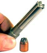
POINT FORMING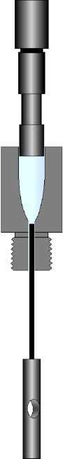 The point forming die is the final stage in forming a typical jacketed rifle or handgun bullet with a smooth ogive. The seated core and jacket are pressed into the die and expanded to the final diameter. It is very important to understand that components to be formed must be slightly less than the bore size of the die, or they will probably stick and be difficult to remove. If a core seating die from a different set is used to make the seated core, or the point forming die is ordered at a different time from the core seater, it is possible for the core seater to be the same size or larger than the point former. This does not work. The point forming die is the final stage in forming a typical jacketed rifle or handgun bullet with a smooth ogive. The seated core and jacket are pressed into the die and expanded to the final diameter. It is very important to understand that components to be formed must be slightly less than the bore size of the die, or they will probably stick and be difficult to remove. If a core seating die from a different set is used to make the seated core, or the point forming die is ordered at a different time from the core seater, it is possible for the core seater to be the same size or larger than the point former. This does not work.Let the die maker know if you are ordering a core seater or point former for replacement, or for a different set (brand, or era of manufacture) than the one you might have just purchased recently from the same maker. Generally, dies made in the same time period by the same people will work together just fine, but with tolerances of only .0001 to .0002 inches between the bores of the two dies, the best fit is done when the die makers have both dies in front of them at the same time and can actually try them with each other. The point forming die has an internal punch that is reduced to the size of a strong spring wire, usually in the .062 to .120 inch diameter range. Very small calibers may use a 0.047 diameter wire. Smaller ejection pins allow the tip to be closed more tightly, but also make it more likely that you will bend the ejection pin if you forget lubrication or use an oversized seated core. There is a practical limit to how small an ejection pin can be made and still have enough columnar strength and cross sectional area to bear upon the bullet material and push it out, without penetrating into the bullet instead. A standard range of diameters has been established for all calibers of Corbin dies. You can order special sizes outside of the standards if you are willing to take responsibility for the results. Most of the time, a reasonably careful bullet maker can get away with using a smaller pin than recommended standard size. Sometimes, not. A person who is not particularly careful or forgets lubrication, mixes up various punches and jackets without much consideration for proper fit, or uses dusty or contaminated jackets will have problems bending pins and poking them through the bullets without ejecting. The smallest calibers (.104, .142, .172) generally use a .047 wire. The calibers from .194 to .257 typically use 0.062 diameter. Those larger than .257 and under .308 normally have 0.072 diameter, while the .308 to .338 calibers most often are equipped with .082. The shape of the ogive, and the tip of the bullet, also affect ejection pin size. A more blunt, round nosed bullet benefits from using a larger pin. Ejection has less potential for problems as the pin is made larger for a given caliber. The drawback is that the point itself can only be closed as small as the ejection pin diameter, without further operations. (To close the tip even smaller, a special hardened lead tip forming punch in a standard lead tip forming die can be used with an open tip bullet.) The ejection pin is fitted with a punch head that is held captive in the press ram, unlike most other internal punches. This is to provide positive retraction of the pin so that the open end of the bullet jacket cannot be formed around it, pinching it in the jacket and preventing ejection against the end of the jacket. Most other operations use an internal punch that pushes on the base of the bullet at full diameter, and has no potential for sticking in the jacket. In the S-Press, the stop pin is pulled from the front of the press and inserted through a hole in the head of the internal punch (which, in the point form die, is sometimes called the ejection pin or ejection punch, even though strictly speaking that is just the wire part of the punch). The easy way to do this is to hold the ejection punch by its wire tip with thumb and forefinger, and hold it alongside the press to position the hole at the stop pin's location. Then, using the thumb and forefinger as a stop, put the punch into the ram and insert the stop pin. If the stop pin went through the hole, you will not be able to pull the punch out by its tip. 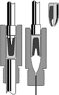 Then align the die over the projecting tip of the ejection wire and screw the die into the ram. Make sure that the ejection wire is lined up and inserted into the hole in the die, or you can crumple up the ejection wire using high leverage 24-pitch threads as you screw the die home. Once the die is installed in the ram, put the full diameter point forming punch in the floating punch holder, lubricate a seated core and drop it open end first into the die. Raise the ram carefully and adjust the punch holder so that the ram is all the way up without any pressure on the bullet. Then align the die over the projecting tip of the ejection wire and screw the die into the ram. Make sure that the ejection wire is lined up and inserted into the hole in the die, or you can crumple up the ejection wire using high leverage 24-pitch threads as you screw the die home. Once the die is installed in the ram, put the full diameter point forming punch in the floating punch holder, lubricate a seated core and drop it open end first into the die. Raise the ram carefully and adjust the punch holder so that the ram is all the way up without any pressure on the bullet.Then lower the punch holder until it can go down no further by hand. Lower the ram slightly, and give the punch holder another quarter of a turn. Keep doing this until you feel some resistance. Lower the ram. If the bullet ejects, examine it and see if the open end is closed as far as you would like, down to the diameter of the ejection pin. If the bullet does not eject, you may need to close the tip a little further so that the ejection pin can press on the end of the jacket. This is especially true of hollow point bullets, which have nothing in the middle for the ejection pin to work against. If you make a bullet design that has a deep cavity or hollow point and will not eject because there is nothing for the ejector pin to touch, a special extra long ejection pin can be made. This long ejection pin will probably not work on normally closed tips, as the pin would be projecting inside the bullet. The tip would be closed on the pin, sticking the bullet to the pin. But for a deep and large hollow point, the long ejector may be the only good answer. (Another is to put a plastic ball in the tip to use for ejection, and either leave it in place or adjust so that it comes out easily.) |
Lead Tip Bullets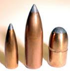 To make lead tip bullets, you can just use the same 3-die set as you do for open tip, but seat a longer (heavier) core in the same jacket, so that the lead will be extruded out the tip when you form the ogive. When the bullet is ejected, the ejection pin leaves a small flat spot on the tip. If this is objectionable, you can shape the tip with a LT-1 Lead Tip Forming Die. To make lead tip bullets, you can just use the same 3-die set as you do for open tip, but seat a longer (heavier) core in the same jacket, so that the lead will be extruded out the tip when you form the ogive. When the bullet is ejected, the ejection pin leaves a small flat spot on the tip. If this is objectionable, you can shape the tip with a LT-1 Lead Tip Forming Die.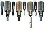 Adding a LT-1 lead tip forming die to the FJFB-3 3-die set makes it into a 4-die set. We give this the catalog number LTFB-4-S (for -S type dies) or LTFB-4-H (for -H type dies). You can add a LT-1 die yourself at any future date, of course. All we need is a half dozen sample bullets from your point form die, with the desired amount of exposed lead showing. Then we can make a punch that exactly fits the tip and shapes it the way you want (rounded, needle-pointed, whatever you choose). Adding a LT-1 lead tip forming die to the FJFB-3 3-die set makes it into a 4-die set. We give this the catalog number LTFB-4-S (for -S type dies) or LTFB-4-H (for -H type dies). You can add a LT-1 die yourself at any future date, of course. All we need is a half dozen sample bullets from your point form die, with the desired amount of exposed lead showing. Then we can make a punch that exactly fits the tip and shapes it the way you want (rounded, needle-pointed, whatever you choose).The LT-1 die is just slightly larger than the bore of the point form die. It is specific to a caliber, like most of the dies. But the tip shape itself is controlled by the internal punch alone. So, you can get one LT-1 die for a given caliber, complete with one tip shape, and add more internal punches for other tip shapes later. A good example would be a semi-spitzer with a rounded tip, a flat lead tip, and a full spitzer tip with a sharp point. This could be done with one LT-1 die, and two extra internal punches. The external punch fits the base of the bullet. It is identical to the external punch for the PF-1 poindt form die. We mark it "L" for Lead Tip, but if you should lose or damage your point forming external punch, you can use the external lead tip punch in the point form die and vice versa. LT-1 dies are marked with the diameter (caliber) and the letter "L". The internal punch is marked with "L", the caliber, and a designation for the ogive shape such as 6-S, 4-S FT, or RN. We don't try to write every detail of the shape on the punch, as there isn't room. Just the basic shape info is indicated. You can quickly tell by making a lead slug in the die if you need more info. For operating details, click here. |
 Rebated Boattail Bullets Rebated Boattail BulletsThe RBT is a low drag bullet that can increase the BC of supersonic bullets by up to 15% over flat base, and subsonic bullets up to 40% over flat base. (The effect of base drag is a larger percentage of total drag below the speed of sound.) Compared to a conventional boattail, the RBT has up to 15% better grouping potential based on muzzle blast induced dispersion: the rebate tends to break up laminar flow of muzzle gasses so the bullet can shoot through the clear "eye" of an expanding ring of gas, rather than being forced to fly through a turbulent ball of gas focused in front of the muzzle. Other advantages include a quicker "release" of the bullet from the transitional zone where the gas is just beginning to escape from the muzzle, reducing the potential "tipping" caused when gas escapes faster on one side than the other, and somewhat increased bore life due to a better seal than a tapered boattail junction against the rifling, which reduces gas leakage and jet cutting of both the bullet and the barrel ID. Any die set with the letters "RB" or "RBT" in it includes two special dies, the BT-1 and the BT-2, as well as a special external punch for the point forming die to match the BT shape. This package of dies and punches is called the RBT-2 add-on set. You can add it to any flat base die set, such as the FJFB-3, to add RBT-making capability. For more details, click here. |
Start writing here...
About Corbin Jacketed Bullet Making