A Section Subtitle
Write one or two paragraphs describing your product or services. To be successful your content needs to be useful to your readers.
Start with the customer – find out what they want and give it to them.
Corbin builds both the JRD-1 and JRD-2 jacket reducing die sets, each in type -S (for the 5/8-24 ram S press with 7/8-14 die threads) and in type -H (for the 1.0-12 ram H press with 1.5-12 die threads). The JRD-1-S and JRD-1-H dies are suitable for simple reduction of a commercial jacket or a tubing jacket made with the Corbin CTJM-1-H or CTJM-1-S Copper Tubing Jacket Maker kits.
The amount a jacket can be reduced in one pass depends on the wall thickness and diameter, and is somewhat limited by the resulting draw length. When the jacket wall does not need to be drawn thinner, and the amount of reduction is not large, the JRD-1 die works very well for light to moderate volume use (home and hobby level). Normally, you can draw a jacket down to 70% of its original size (a reduction, in other words, of 30% in diameter) in one pass.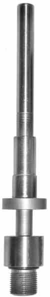
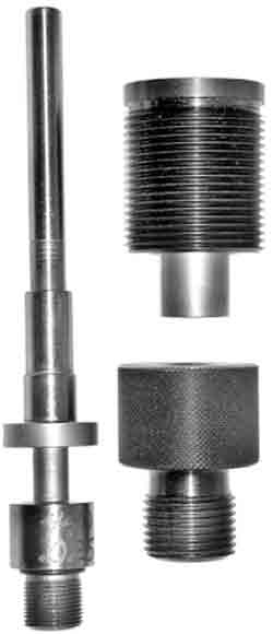
The JRD-2 dies, on the other hand, are designed with longer punches, tougher materials, and a different, more complex geometry. Current production versions use a sliding guide bushing which mates with a guide nest in the die mouth, to positively align the punch, jacket, and die before reduction takes place, insuring excellence in wall concentricity. They are more expensive to build, requiring more time consuming machine work and heat treatment because of the design and materials. But they provide longer life in heavy commercial volume use, as well as a more precise control over wall thickness. The JRD-2-S is provided with the Corbin JMK-1-S jacket making system, and is also available for drawing tubing or commercial jackets. The design of the JRD-2-S and JRD-2-H punches provides a pair of wrench flats near the threaded base, to allow easy removal from the ram or the ram adapter. The JRD-2 design is used when the jacket wall thickess is reduced, as well as the jacket diameter. If the jacket wall remains the same thickness after reduction, then normally a JRD-1 can be used.
The same 5/8-24 thread is used on the hardened tool steel punch for both the JRD-2-S and the JRD-2-H dies. The difference is that an adapter unit, the CHP-SPA, is used with the -H presses (CSP-2 Mega Mite, CHP-1 Hydro Press, and CSP-2H Hydro Junior). This adapter (Corbin Hydro Press -S Punch Adapter, or CHP-SPA) allows a 5/8-24 threaded punch to be used in the 1-inch x 12 threaded rams of the larger Corbin presses. However, the actual punch dimensions for a JRD-2-H can be longer than would work in the shorter stroke CSP-1 S-Press, allowing for longer draws. The JRD-2-H die itself is also a larger tool with longer alignment areas. When practical, the -H dies should be used with the -H presses.
However, the JRD-2-S punches can be physically threaded into the same adapter unit and also used in -H presses, with the same length limitations as would be true in the -S press. Likewise, the -S draw die will thread into the optional RLA-B Reloading Adapter Bushing, which allows 7/8-14 threaded dies to screw into the 1.5-12 thread of the larger Corbin -H presses. This means that you can normally use a JRD-1-S or a JRD-2-S draw die in any Corbin press, using the appropriate adapters. It does not mean that the -S dies will be an exact replacement for a similar -H die. Issues of punch and die length and the added alignment benefits mean that a type -H draw die normally gives higher quality control in regard to jacket wall thickness variation, at least in those applications where jacket walls are reduced during the draw.
The best quality control is accomplished by using the least number of steps that will allow the draw to take place without undue effort. Drawing a .452 diameter cup to .357 caliber may require two draws (from .45 to .40, and from .40 to .357) because the material being drawn may be broken through with the draw punch if too much force is required on the inside of the base. Force is lowered by taking a smaller reduction. For the sake of reasonable production, the number of draws needs to be minimized. Therefore, the die sets are designed with five factors in mind:
- Strength of material to handle drawing pressure on the base.
- Amount of time to make additional draws.
- Jacket wall concentricity and practical tool geometry.
- Amount of pressure available through the draw cycle.
- Resulting length of drawn jacket relative to press stroke.
Each jacket will be made with exactly the same volume of metal before and after reduction. The metal that was used in the circumference of the jacket will be moved into a new length. If the walls are also reduced, additional pressure is required and more metal is moved into the length. The base itself usually remains nearly the same thickness, but the walls are stretched and may be thinned, depending on the difference in diameter between the punch and the die. Steps and tapers may also be introduced in the jacket wall by design of the punch geometry.
If the jacket is made too long it may not be possible to remove it from the punch easily. The jackets are removed on the down stroke, by passing the jacket mouth above the top of the die. The manual presses, and especially the -S press, has either a 2-inch swaging stroke or a 4-inch reloading stroke (depending on where you place the ram pivot pin). The 4-inch reloading stroke is used for nearly all jacket drawing operations. In order to easily slip a jacket over the punch, at least the length of the original jacket must be left from the punch tip to the bottom of the die, when the ram is in the down position.
If for example you want to reduce a .7 inch long .45 jacket to .338 caliber, the first draw will probably be to .400 diameter, and you will need at least .7 inches from the tip of the punch to the bottom of the die in order to load the jacket. The draw itself would be another .7 inches if the jacket did not get longer, but it does. The jacket may grow to a length of 1 inch or more at .400 diameter. Therefore, the press needs to have a very minimum of 1.7 inches of ram travel, to lift the jacket into the die mouth and then to push it past the constriction within the die. But in addition to this actual reduction work, the press must also lift the drawn jacket so that the mouth of the jacket can move past the sharp, squared edge of the die top. The jacket will then be able to spring outward slightly as pressure is released. On the down stroke, the jacket will be firmly squeezed on the punch, but the jacket mouth will contact the flat top of the die instead of pulling back through the hole.
This extra travel to move the jacket past the constriction and through the die, out the top, so it can be extracted automatically on the down stroke, will require another half inch to an inch of travel, depending on the die design and requirement for aligning the jacket (no guidance after drawing might result in a banana-shaped jacket). Now we have used as much as 2.7 inches of ram movement. Most manual presses will have 80% of their power when the ram position is 20% away from the end of the ram travel (log function power curve). If the ram has a 4 inch travel, then the press would be up to 80% of full power by the time the ram was 0.8 inches from the end of stroke.
If the press generated 10,000 pounds of ram thrust at the end of its stroke, and you needed 9,000 pounds of ram thrust to draw a given jacket, at 0.8 inches from the end you would only have 8,000 pounds available and couldn't do this job. If the jacket were 0.7 inches long to start, you could just barely draw the original length and then you would run out of stroke before the rest of the metal was pushed through the die (jacket would be two-diameter, yet no more stroke available to finish the draw). For this draw you would need a press with longer stroke, and also with higher leverage (which would mean, a longer handle, since the power is set by a ratio of handle travel to ram travel). The Mega-Mite, or the Corbin Hydro Press, might be required.
In short, there is considerable design work that goes into each set of dies depending on what you start with, and where you want to finish. Some draws are simple, with one stroke in a normal length press. Others are more complex, and may have to be broken down into two or more steps with additional dies and trimming steps in between. Working with your die-maker insures that you will get the best results at least cost. The JRD-2-S and JRD-2-H dies provide you with additional wear resistance, capability of precision jacket wall thinning, and potentially more accurate jackets.
Start writing here...
About Corbin Jacket Reducing Dies